
The short answer
Sketch permanent landmarks and the station first. Mark only known wire routes, use a different line for uncertain sections, and label every visible joint or repair. A useful map shows what you do not yet know.
Applies toExisting physical-wire Automower installations. This is a documentation method, not a cable locator, survey or installation design. EPOS and other virtual boundaries need their own procedures.
A mower fault can become harder to investigate when the installation exists only in someone’s memory. This guide shows how to turn photographs and observations into a record that a future owner, gardener or servicing dealer can understand.
01Anchor the sketch to things that stay put
Draw the charging station, building edges, paths and fixed beds. Add an orientation arrow of your own, such as “view from patio towards gate”, so another person can read the sketch without guessing. If the drawing is not to scale, write that on it.
Choose one permanent corner as your reference for visible points. For example, “joint J1 beside the third paving slab from the gate” is more repeatable than “near the shrubs”. If taking measurements, record the endpoints and units. Approximate observations should stay labelled approximate; a neat drawing is not evidence of accuracy.
02Give known and uncertain routes different marks
Use a solid line for a route established by reliable installation records or visible evidence, a dashed line for an estimate, and a question mark for an unknown section. Keep the evidence beside the label: “photo P2, before turf was laid” or “owner recollection only”. These are YardOnAuto recording conventions, not manufacturer symbols.
A line drawn between two known points can still hide a detour. Do not use an inferred route as permission to dig, edge or aerate. If work will cross an uncertain section, have it located before work begins. Preserve the unknown area on the sketch rather than making the route look complete.
03Record labels without experimenting with the wiring
Husqvarna’s wire-break guidance recommends checking station connectors and known splices and referring to the installation map. Photograph existing labels before approved disconnection and use the exact manual to identify them. Distinguish the boundary from any guide wires in your record.
Do not swap connectors to work out which line your sketch represents, and do not cut the loop merely to add a new label. Cable isolation and wire-break searches are separate model-specific procedures. The map should organise evidence for those procedures, not quietly introduce a new wiring test.
Three places to look before lifting the lawn
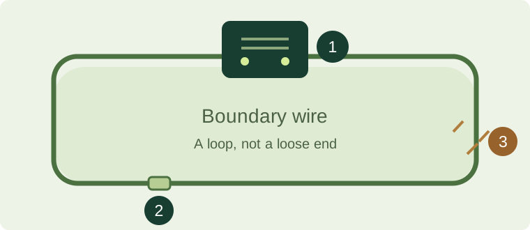
- 1Station connections
- 2Existing wire joints
- 3Recently disturbed edges
Based on source 1.
04Give each known repair a name and an outcome
Assign simple labels such as J1, J2 and J3 to known joints. For each, write the date if known, the location reference, the photograph identifier and whether the information was observed directly or reported by someone else. Add the material or repair details only when you can identify them.
Keep old entries when a repair is revised. “J2 replaced, date, dealer invoice reference” makes more sense than deleting the earlier location. A joint that looks intact has not been electrically proven intact. Keep appearance, test result and repair action as separate notes.
05Worked handover: a new bed beside the gate
Illustrative scenario: a mower previously ran normally, a bed was extended near the gate, and the station now flashes blue. The owner’s map shows a confirmed joint J1 at the patio but only a dashed route beside the new bed. The handover records the timing, exact mower error and station light. It does not state that J1 or the new bed is definitely responsible.
The installer can now see which part of the record is reliable, where recent work occurred and which checks have already been performed. If a repair is made near the gate, add its location and the normal-operation check result. Keep the original fault note so that a recurrence can be compared with the earlier event.
06Store a usable copy with the maintenance records
Put a dated copy with the mower manual and tell anyone doing garden work that uncertain areas require locating. Photograph the paper as a backup if useful. Avoid including alarm PINs or account passwords in a map you may hand to a contractor.
Update the sketch after landscaping, station relocation or a documented repair. If the installation is being redesigned, return to the manufacturer’s planning instructions and the exact model manual: this record does not establish boundary distances, passage widths, slope limits or a compliant guide-wire layout.
Based on source 2.
Take a useful record away
Wire-map handover record
Use with your sketch. Mark confidence explicitly and keep unresolved sections visible.
- Mower model; map date; orientation and scale or not-to-scale note
- Station and fixed landmarks; reference point for measurements
- Known routes; uncertain routes; evidence or photo references
- Joint IDs, locations, dates and repair records
- Fault observation; checks completed; result and next action
Use your browser’s Print command, or “Print guide” at the top, to print or save a PDF.
Check the original guidance
Sources & verification
Sources checked on . First published . Follow the manual for your exact model if its instructions differ.
- Husqvarna: wire-break investigation, connectors, splices and installation maps
- Husqvarna: physical boundary-wire installation planning
Diagrams and the order of checks are YardOnAuto’s explanatory presentation of the cited guidance, not manufacturer installation drawings.
Our editorial method